
Create a factory and set up factory resources
ADMINISTRATOR

An administrator (or a user with administrative rights) sets up your virtual factory and factory resources. The Factory Resources area of FactoryLogix Office visualizes the physical assets and resources available for production on the factory floor. A workstation is one of the key assets you need to define when you set up factory resources:
Each workstation may be grouped into lines or clustered workstations
Note
You need to configure lines in order to use the Line Monitor area of FactoryLogix Operations.
Each line or clustered workstation may be grouped into an area
Areas may be grouped into a factory
Note
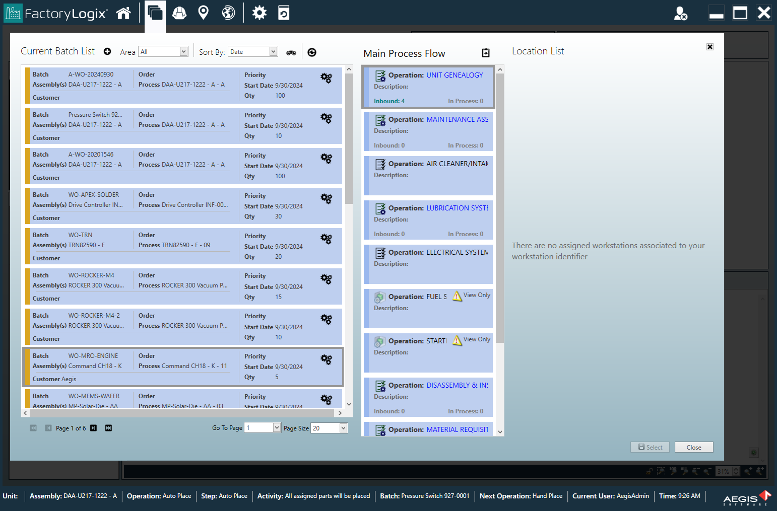
Areas are used in the Advanced Batch Management section of the shop floor to prioritize batches by factory area.
After you create and configure your factory, you're ready to set up workstations to generate machine programs for placement and inspection equipment in the factory.
Create a factory and resources
Log into FactoryLogix Office.
Select Templates and Standards
 > Factory Resources.
Select the New
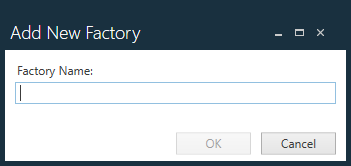
 button on the left side of the window, then select Factory from the drop-down.
Enter a name for the new factory, then select Save.
After you define a factory, you can add an area or a line.With the new factory selected in the tree on the left side of the window, now select the Add
button under Asset List, select Area, name the area, then select Save.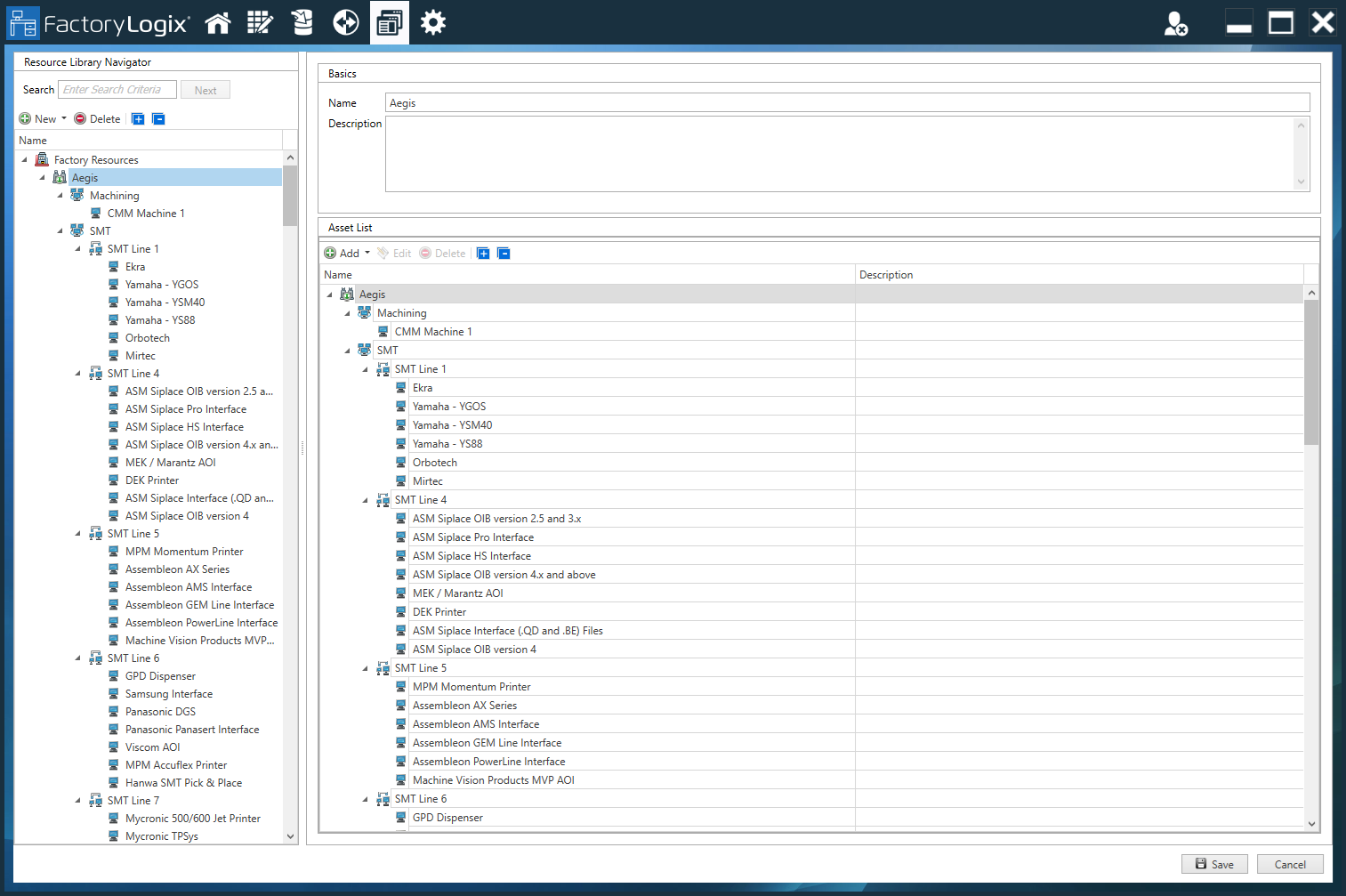
Repeat Step 5 for each area, line, workstation, clustered workstations, and other resources you want to add to your factory.
Set up a workstation
After you create factory resources, you create and set up individual workstations (to enable machine programming for electronics, for example).
Select a workstation or clustered workstation from the factory tree on the left side of the window.
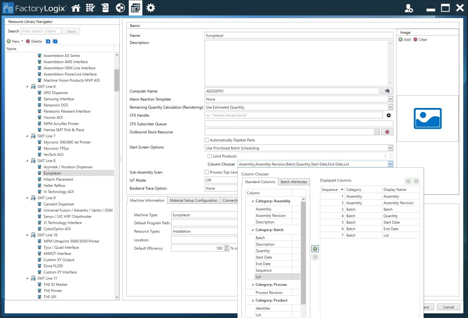
On the right side of the window under Basics, enter a Name for the workstation.
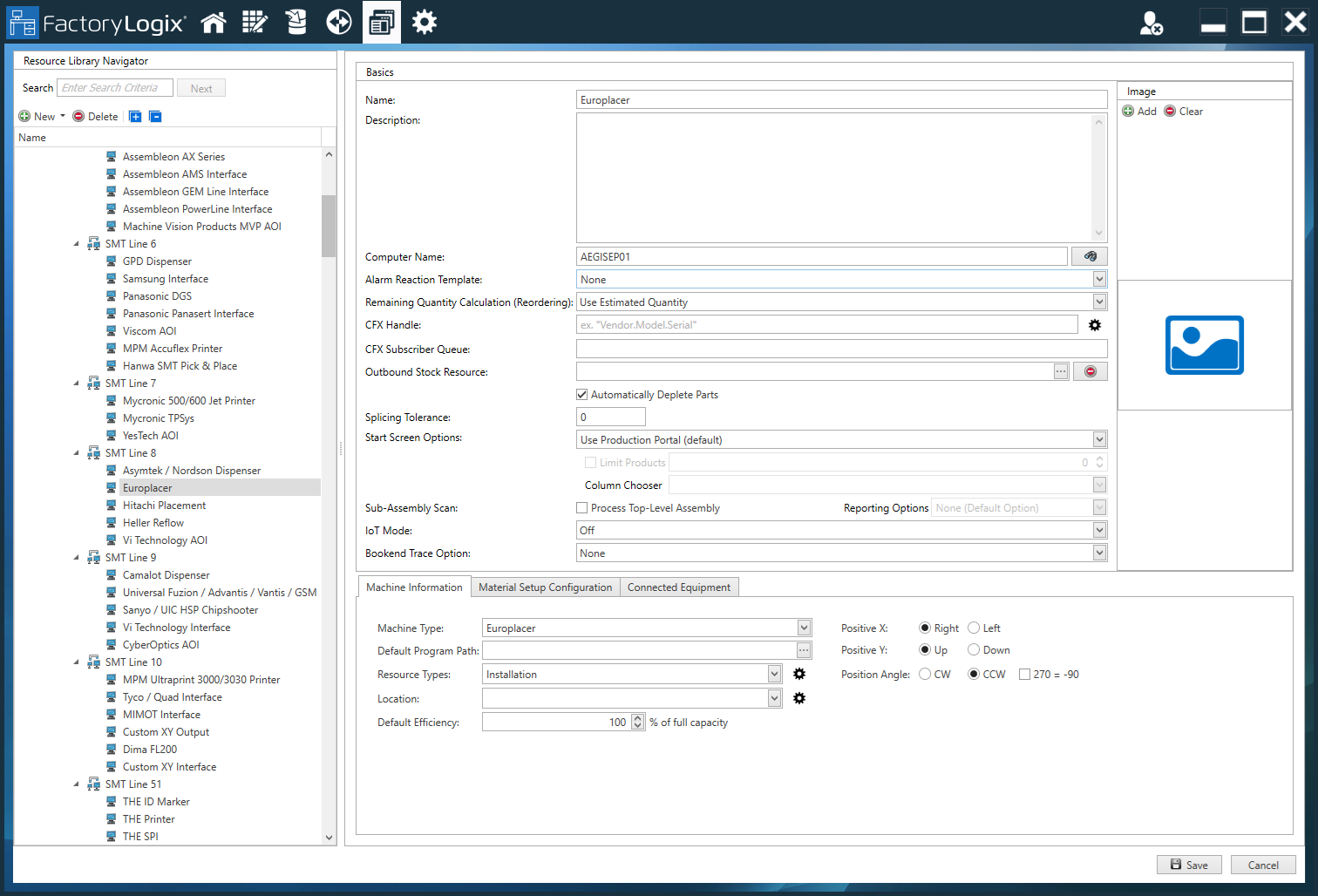
Enter a Description for this workstation. (Although a description is optional, it is often very useful, especially if multiple, similar workstations are being used.)
(Optional) Select the Add
button, then locate and select an image of the workstation.Enter a Computer Name.
Important
The Computer Name setting specifies which computers can use this workstation in order to view the operation (computer names are separated by semicolons). If the operation has a resource restriction and the computer currently being used is not listed in the Computer Name field, the operation cannot be opened in FactoryLogix Operations. (Resource restrictions are specified on the Resource Restrictions tab of the Update Operation dialog. See Add a new operation to a process flow for more information.)
The following illustration shows the message an operator will see in FactoryLogix Operations when an operation has a resource restriction and the computer currently used is not listed in the Computer Name field:
If you want to use an alarm reaction template for this workstation, select one from the Alarm Reaction Template drop-down. (For more information, see Alarm triggers, reactions, and alarm reaction templates.)
To specify the method used to calculate remaining parts for this machine for reordering purposes, select Use Estimated Quantity or Use Actual Quantity from the Remaining Quantity Calculation (Reordering) drop-down.
(Optional) Next to CFX Handle, enter the Connected Factory Exchange (CFX) handle name that identifies this machine in the CFX network.
Note
A CFX handle identifies each machine/endpoint participating in a CFX network. Each machine/endpoint must have a globally unique CFX handle. To achieve this, the CFX standard recommends the following convention CFX Handles: <VENDOR>.<MODEL>.<SERIALNUMBER>
(Optional) Next to the CFX Subscriber Queue option, enter the name of the CFX subscriber queue to be used for this factory resource.
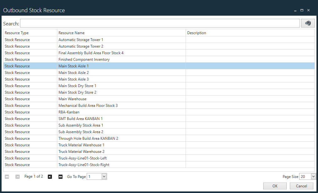
Select the ellipsis (...) next to Outbound Stock Resource, select a stock resource from the list (or search for the desired resource using the Submit Search
 button, then select OK.
The Outbound Stock Resource option allows you to set a stock resource on a workstation, workstation cluster, a line, or an area. This will be the stock resource where the material will be stored before being transported to the next location via a transport order. The system uses the workstation identifier to locate the appropriate workstation for the assigned stock resource and will look until a resource is found.
(Optional) Select the Automatically Deplete Parts check box to deplete electronic parts automatically, then specify a Splicing Tolerance value (for splicing part reels only).
Next to Start Screen Options, select Use Production Portal (default) or Use Prioritized Batch Scheduling.
Use Prioritized Batch Scheduling limits the number of products displayed to operators on the FactoryLogix Operations start screen. You select the Limit Products check box, then enter the number of products to be displayed to the operator at one time.
If you select the Column Chooser option, you can select the specific columns to display for each product on the Start screen in FactoryLogix Operations.
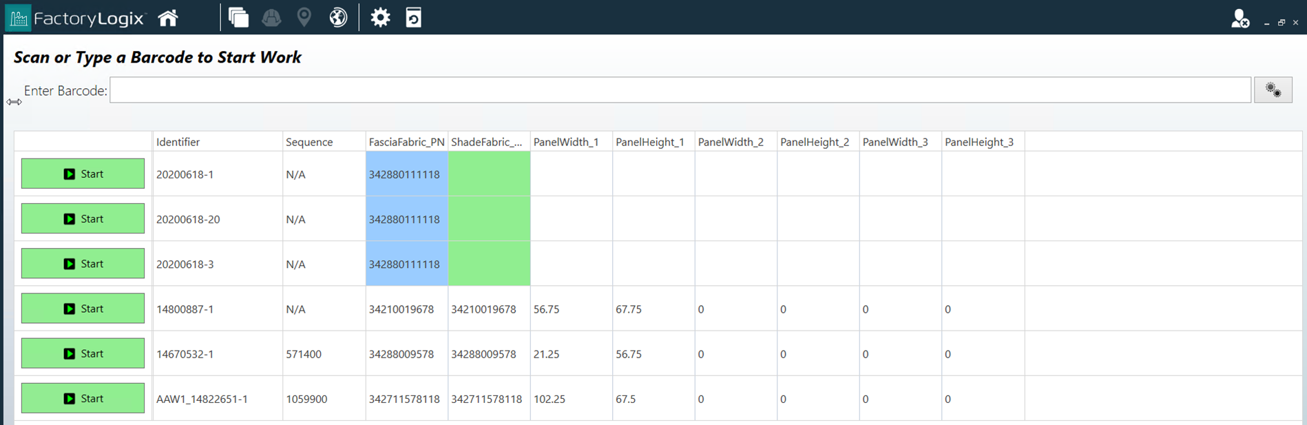
Do one of the following for the Start Screen Options selections that determine how the Operations start screen looks:
Select Use Production Portal (default) to show all of the serial number/batches on the FactoryLogix Operations start screen.
Select Use Prioritized Batch Scheduling to determine the workstation based on the Computer Name you entered earlier in this procedure.
Having the workstation name, the operation is determined based on the resource type specified in the Update Operation dialog.
The FactoryLogix Operations Start screen will display all of the serial numbers/batches that are inbound to the defined operation for the workstation where FactoryLogix Operations is executing.
Next to Sub-Assembly Scan, select Process Top-Level Assembly to do the following:
In FactoryLogix Operations, when a request to start a WIP transaction is initiated and the workstation at which that request originated is known, the system will identify the UID of the ultimate (top-level) parent of the assembly whose UID was provided in the WIP Start request. After the UID of the ultimate parent assembly has been identified, the WIP Start request is updated to reflect the UID of the ultimate (top-level) parent assembly before normal processing continues.
Important
The Process Top-Level Assembly option will only work if the workstation is identified and the option only supports single serialized units (that is, running multiple units for an operation is not supported).
Note
WIP transactions can be recorded from a variety of sources:
FactoryLogix Operations
A CFX xLink adapter
A CAMX xLink adapter
The xTend API
An ultimate (top-level) or parent assembly refers to the highest-level assembly of which a child assembly is a part. It is the ultimate parent UID that is expected to be scanned at the start of an operation as that unit is moving through production but sometimes its UID is not readily accessible. For example, when starting a WIP transaction, the system will accept the UID of any sub-assembly (LMN456, PQR678, STU789, or DEF345) in order to start a WIP transaction for the serialized unit at the top of the hierarchy, unit ABC123.
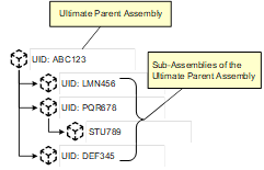
As a result, when the Process Top-Level Assembly setting is checked, to start a WIP transaction of the ultimate parent assembly (unit ABC123 in Figure 1 above), any of the UIDs shown could be used (ABC123, LMN456, PQR678, STU789 or DEF345).
Use the Reporting Options drop-down to select the desired reporting options that affect how WIP-related messages (messages relating to the starting, pausing, finishing or validation of a serialized production unit) are displayed in FactoryLogix Operations:
Supplied & Processed UIDs presented before Message - Standard WIP-related messages in FactoryLogix Operations will contain the following before the message:
Supplied -<UID>, Processed -<UID>
Supplied & Processed UIDs presented after Message - Standard WIP-related messages in FactoryLogix Operations will contain the following after the message:
Supplied -<UID>, Processed -<UID>
For IoT Mode, select Off (default), Fill Empty Barcodes, or Always Fill Barcodes.
For Bookend Trace Option, select None (default), Bookend Member, or Bookend Finish.
Review the options on the Machine Information tab and make any necessary changes to the options.
Machine Type - Specifies the type of machine interface associated with this workstation.
Positive X, Positive Y, Position Angle
The Positive X/Y values define whether a positive value for the X/Y coordinates mean that the position is to the left/right or above/below the origin point respectively.
The position angle defines whether rotation angles are to be considered Clockwise (CW) or Counter-Clockwise (CCW).
Default Program Path - Specifies the default path for output files for this machine.
Resource Types - Specifies the resources used by this machine. (Select the Edit Resource Types
 button to display a dialog where you can modify resource types.)
Location - Specifies the physical location of the machine (a specific factory, for example). Select the Manage Locations
button to add or delete locations.)Default Efficiency - Specifies the percentage of efficiency for this machine at full capacity.
Note
Some machines also define 270 degrees as -90; the check box to the right of the Position Angle allows FactoryLogix to take this into consideration during Machine Programming.
Review the options on the Material Setup Configuration tab and make any necessary changes to the options for this workstation:
Select Requires Location Scanning to ensure that this workstation's location barcode must be scanned. Use the buttons on the right side of the dialog to add/manage location attachment points (Location Barcode and Location Name).
Select Default Bulk Load Mode to specify how materials are bulk loaded onto this machine when existing parts are depleted: Do Not Load, Splice, or Replace.
On the Connected Equipment tab, you can manage connected equipment such as torque drivers, laser printers, testing devices, and laser markers.
Note
The Connected Equipment tab provides the same functionality as the Connected Equipment button in the Templates and Standards areas of FactoryLogix Office.
Select the Save button to save the configuration for this workstation.