
Operating inForce
Normal operation
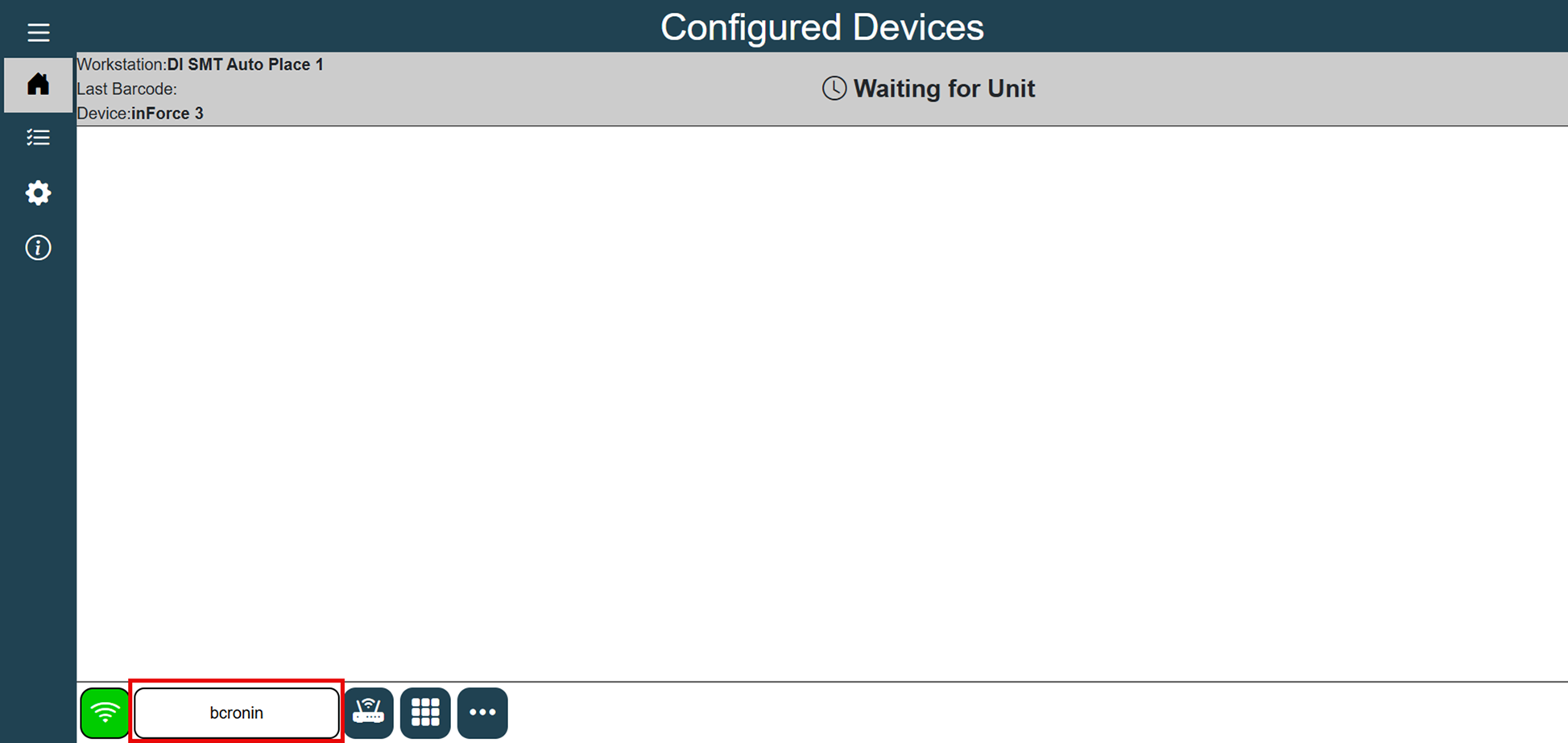
Under normal production, an inForce unit sits quietly with a status of Waiting for Unit—meaning it is waiting for a PCB to arrive and cause the UPSTREAM Board Available signal from SMEMA to close or go high.
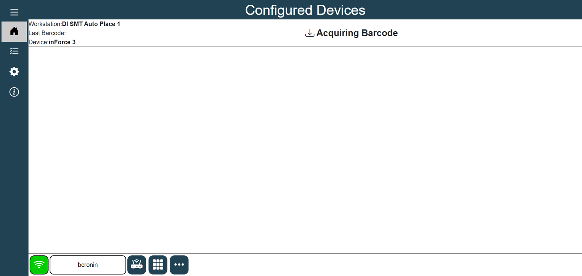
Once this US-BA signal is received, the inForce device will start actively “listening” to the attached and configured barcode scanners for a UID. The display will indicate this by turning white and displaying the message Acquiring Barcode.
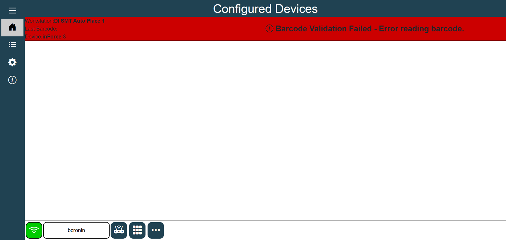
If a barcode is not received in a reasonable amount of time, the device will display an error message that reads Barcode Validation Failed: Error reading barcode. If a valid barcode is received but fails some other validation configured in the xLink adapter settings, the same error message will be displayed with a clear indication as to why the validation failed.
Once a barcode is received which passes all configured validations, the status bar will turn Green and indicate Transfer Pending. This means that the unit now has a validated PCB ready to progress down the line to the next piece of equipment and is now simply waiting for the DOWNSTREAM Machine Ready signal from SMEMA closes or goes high. This would indicate that the downstream machine is ready to accept the PCB. Once the Machine Ready signal is received (so both US BA and DS MR are high) the conveyor is unlocked, the unit will display a status of Transferring Unit and then return to the starting status of Waiting for Unit.
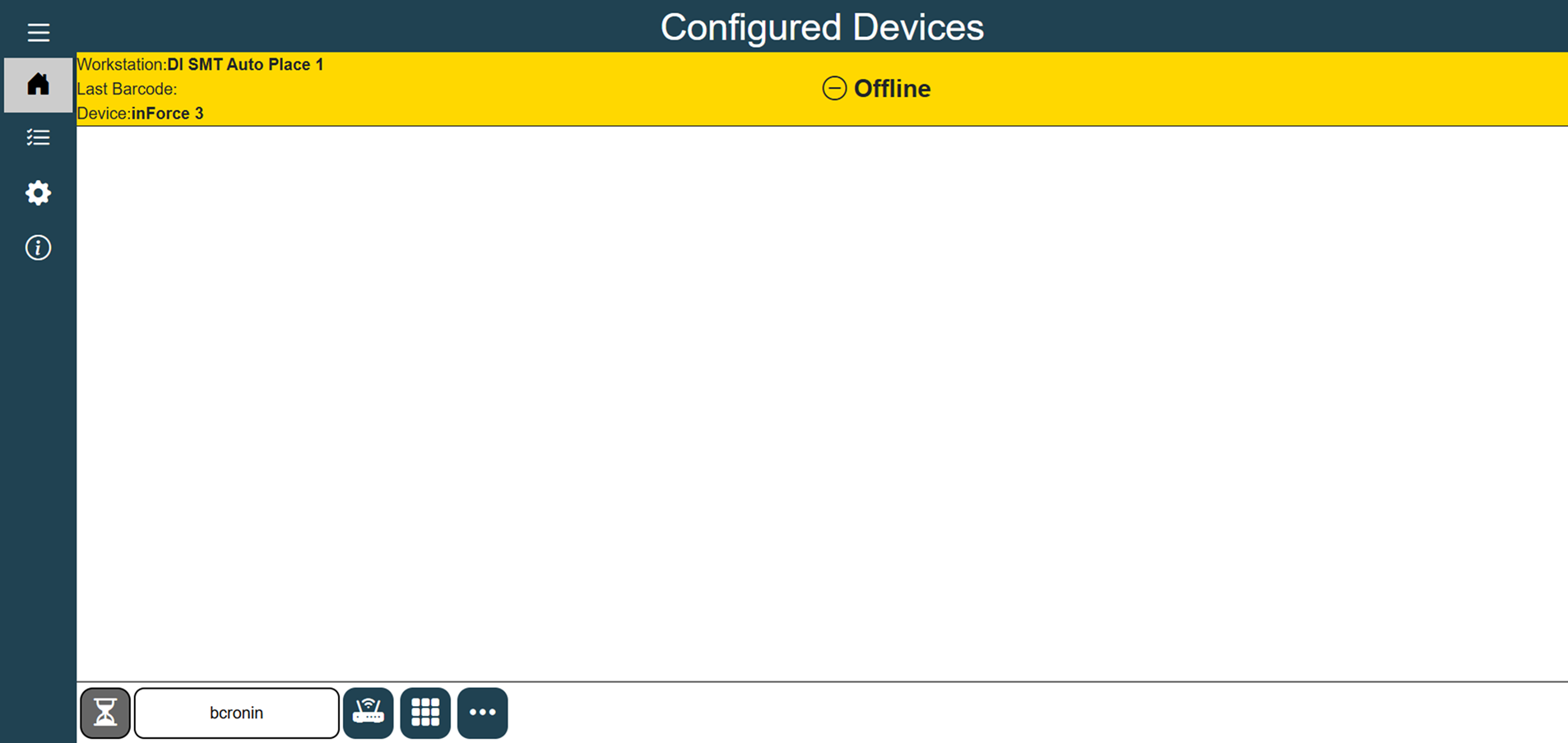
If the inForce becomes disconnected from the xLink Server, the status bar will turn yellow and display a status of Offline.
Bypass mode
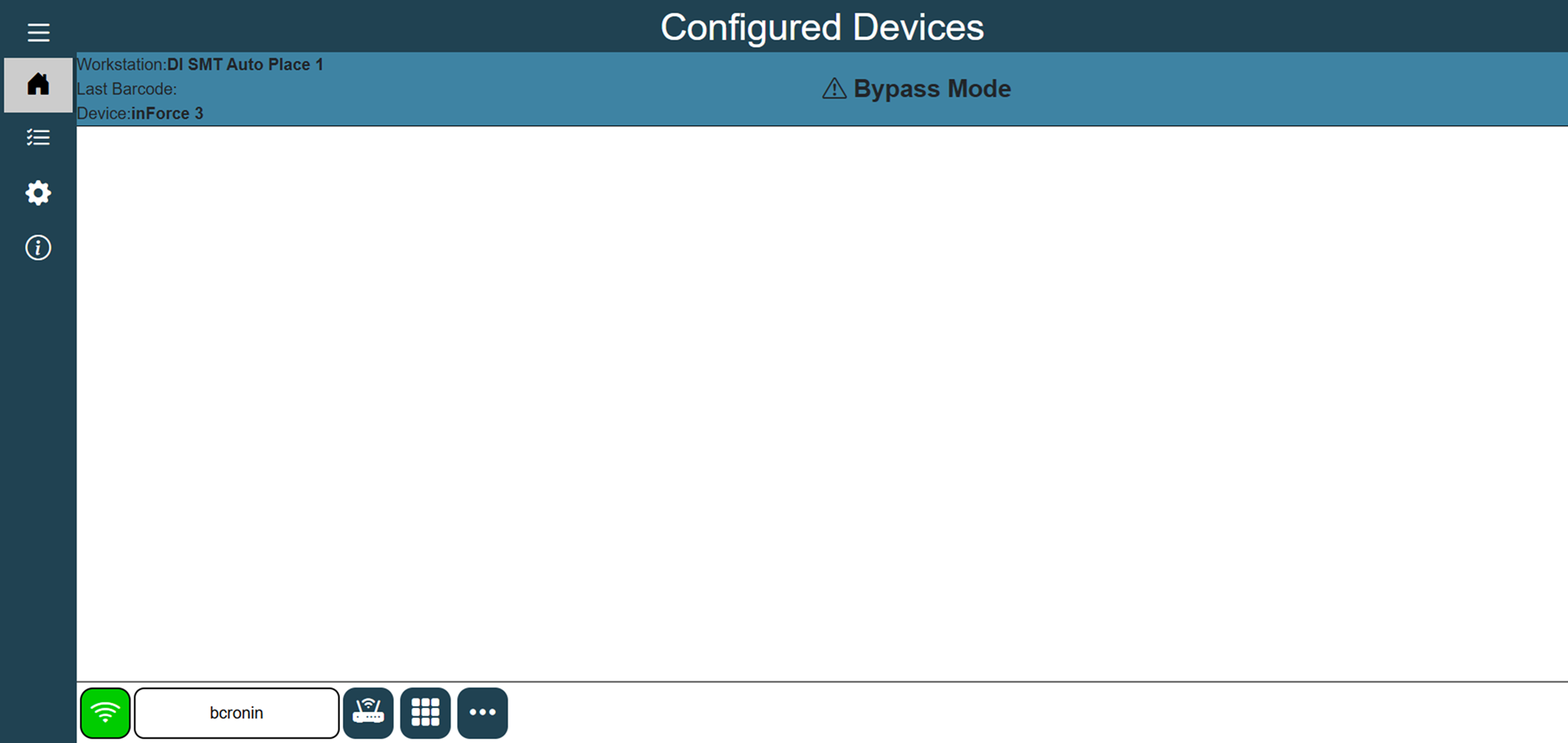
When the inForce device is not being used in production in FactoryLogix Operations, it may be put into Bypass Mode. In this mode, the SMEMA signals will simply pass right through the inForce unit as if the inForce unit was not present.
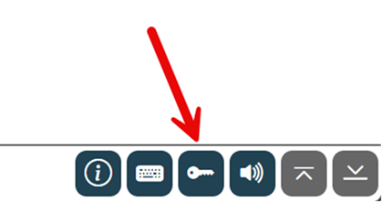
Select the Enter Bypass Mode button in the bottom toolbar of the device configuration screen to enable the Bypass mode.
The status bar will turn blue as a visual indicator.
Audible alarms
inForce 3.0 is capable of alerting operators of an error or alarm condition with an audible alert, similar to the previous generation of inForce. However, the unit does not have a built-in speaker. Instead, users may connect a USB speaker to the device to enable audible warnings and alerts. Here is one example of an inexpensive USB Speaker: USB Mini Speaker
Serial transfer option
inForce 3.0 is equipped with a dedicated built-in seral port which can be used to transfer a scanned and validated barcode to another piece of equipment. The settings pertaining to this serial port can be set in the xLink Adapter settings in FactoryLogix Office (baud rate, stop bits, and so on).
Alarm tower connector
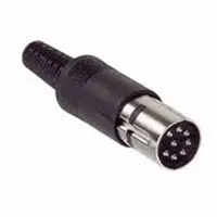
The inForce hardware unit is outfitted with an Alarm Tower connector on the rear of the housing. This connector can be used with a customer-provided light tower to visually display the status of an inForce device from a distance. The connector is a standard 8-pin DIN connector like this one from Digi-Key:
The following pins will be closed (shorted) under certain operating conditions:
Pins 1 and 2 | Green (Operating normally) – Flash in Bypass Mode |
Pins 3 and 4 | Yellow (Unable to connect to xLink Server) |
Pins 5 and 6 | Red (Error Condition) |
Pins 7 and 8 | Audible Alarm (When enabled – accompanies errors) |
Remote monitoring
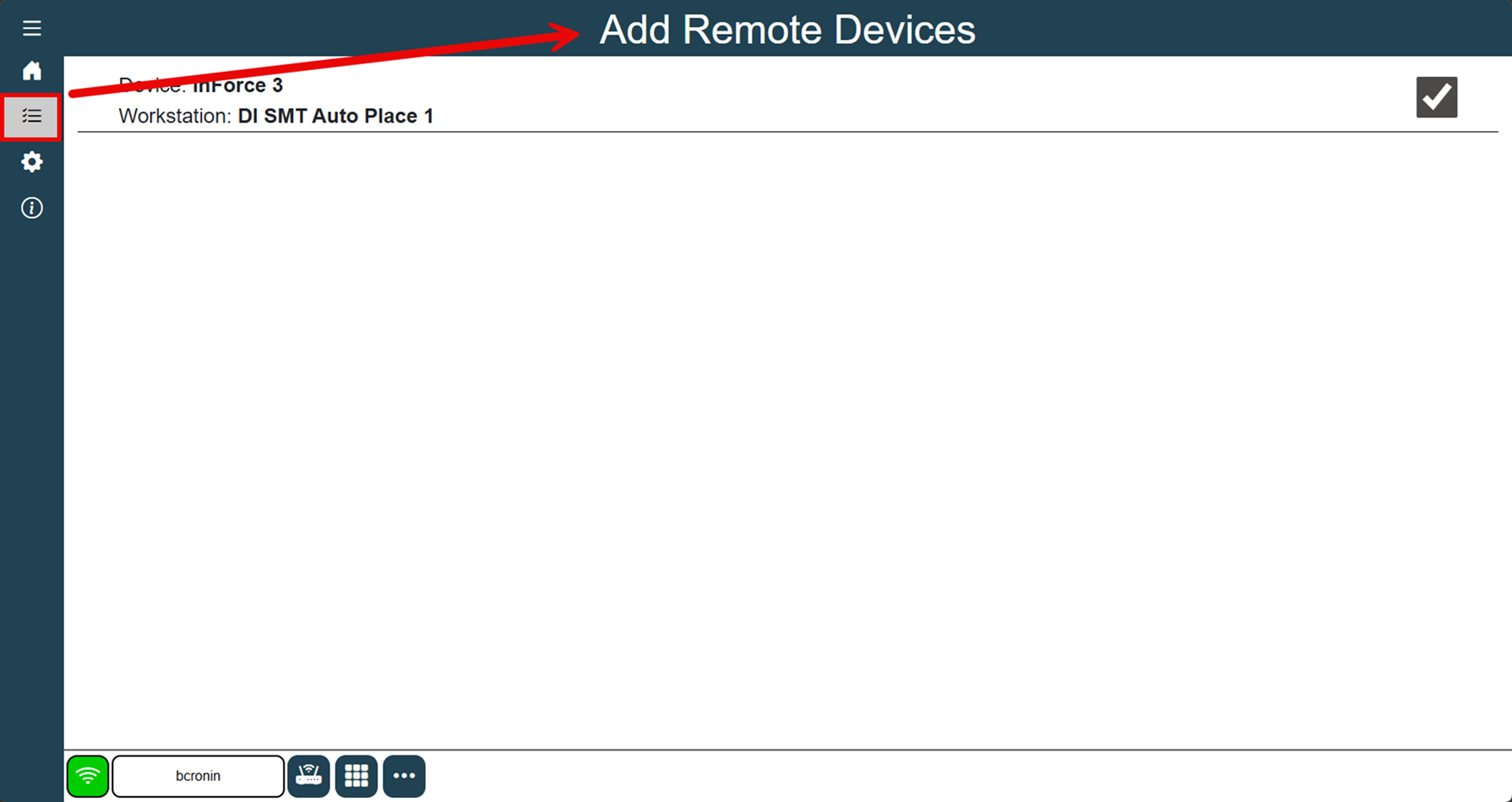
An inForce 3.0 device is designed to operate in “headless” mode, meaning it doesn’t need a display connected to the actual device but may still be monitored remotely. The inForce software itself exposes a webpage which can be used to monitor one or more inForce devices on the same screen. Simply open a web browser and enter the IP address of one of your inForce units. The browser should display the same “home” screen as if you were connected to the device locally. You can add additional inForce units to be monitored by selecting the Add Remote Devices button on the left navigation bar. Select the check box for each device you want to monitor remotely, then return to the Home screen.
Note
You cannot change settings on inForce devices remotely, only monitor their status.
Diagnostics
As there are no external SMEMA Status LEDs on the device as there were in inForce 1.0, there is a tool in the settings screen to assist in diagnosing SMEMA signals and their current states:
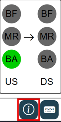
These statuses include columns for both UPSTREAM and DOWNSTREAM (US and DS) signals and are as follows:
BF – Failed Board Available
MR – Machine Ready
BA – Board Available
Updating the device software
Occasionally, new software may be released to enhance and/or add features or functionality to the inForce device. Fortunately, upgrading to a new version of the inForce software is a function built into the device.
Log into FactoryLogix Office.
Select System Configuration > xLink Configuration.
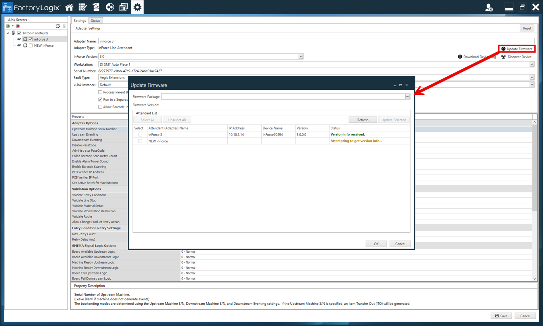
Select one inForce device from the tree, then select the Update Firmware button.
Browse for the NUPKG provided by Aegis.
Once selected, the list will compare the version of the NUPKG file with the versions of each inForce on your server. You may choose to update one at a time or select several to update them at once.Select OK and the selected devices will be updated and restarted automatically.