Initial setup and installation
Important
The new 3.0 operating system and software are still running inside the inForce 2.0 hardware, which is why the silkscreen naming wasn't updated on the hardware case—it is still the same, very capable hardware as the previous generation.
Add a new xLink adapter instance
Before the inForce device can be used in production, a new xLink adapter instance must be added to an existing xLink Server. Your Aegis Deployment Engineer will help with this step. Once an Aegis Line Attendant xLink Adapter instance is created on your xLink Server, you may power up the inForce device.
Complete the device connections
Warning
Use extreme caution—do not reverse the SMEMA connections!
Connect the SMEMA cable from the OUT of the previous conveyor or machine to the UPSTREAM connector on the top of the device—this should be the machine or conveyor from which inForce is receiving the PCB from.
Connect the DOWNSTREAM connection to the next piece of equipment’s IN—this is the machine to which the inForce unit will be transferring the PCB after a valid barcode is scanned.
Connect the Ethernet jack to your company’s network.
Important
This network connection must be on the same subnet as the xLink Server in order for the discovery mechanism to work, as UDP packets cannot normally traverse subnets. By default, inForce will use DHCP to obtain an IP address. See the appendix at the end of this guide for details on advanced IP configuration if needed.
Connect one or more barcode scanners to the USB ports.
Connect the power.
Warning
Only use the 5V power adapter which was supplied with the inForce device. Use of any other power supply will void the warranty.
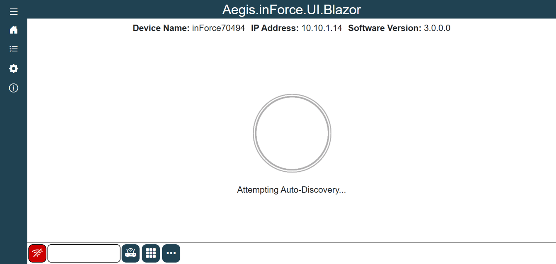
The first time the inForce device powers up, the device is given a name, which will be “inforcexxxxx” where xxxxxx is a 5-digit random number.
At this point, the inForce device will be in Discovery mode and is ready to be discovered by the xLink Server, as shown in the following illustration:
 |  |
|---|
Connect to an xLink Server
With a single inForce unit in Discovery mode, log into FactoryLogix Office.
Navigate to the System Configuration area, then select xLink Configuration.
Add a new xLink Adapter to your default xLink Server on the Settings tab.
Set the Adapter Type to inForce Line Attendant, then select OK.
The new inForce adapter should be added to your xLink Server.Be sure the inForce Version drop-down selection is set to inForce 3.0.
Select the Workstation this inForce unit is associated with.
Select the Discover Device button on the right side of the window.
The inForce unit which is currently in Discovery mode is found and associated with the newly-added adapter instance—provided the device is on the same subnet as the xLink Server.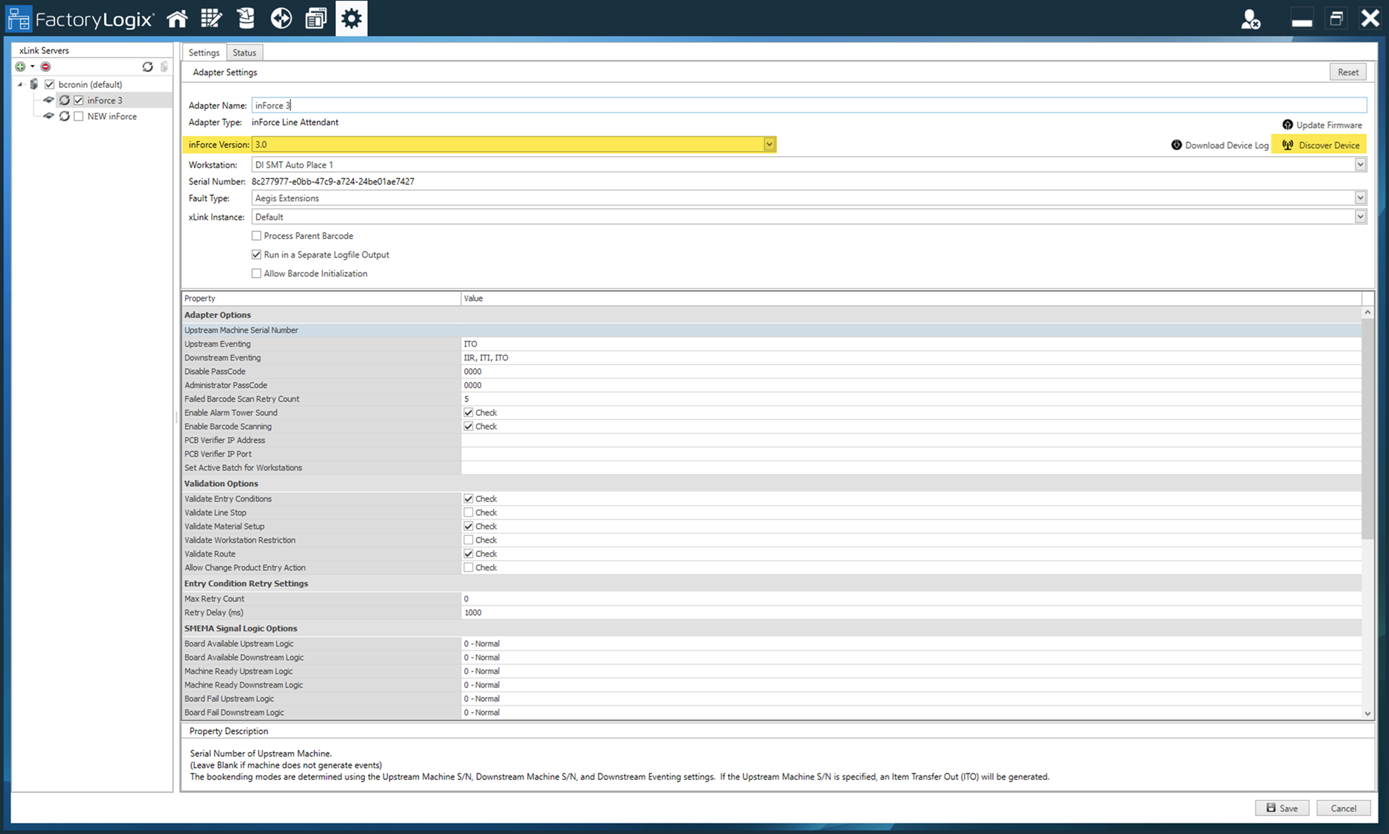
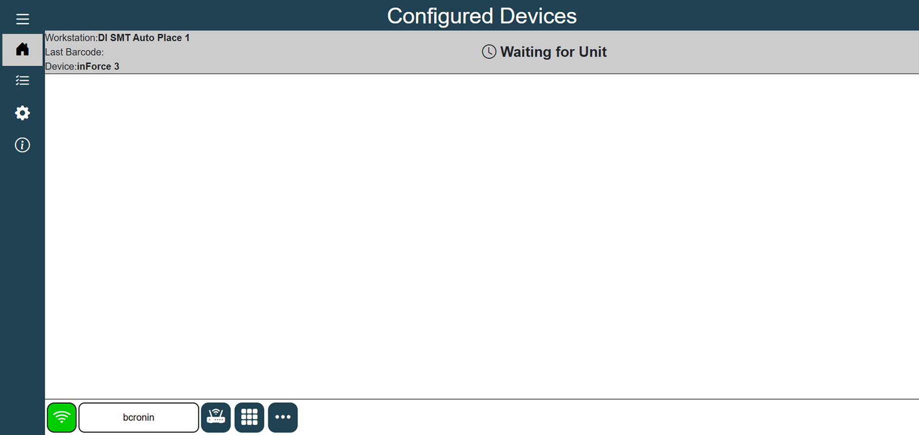
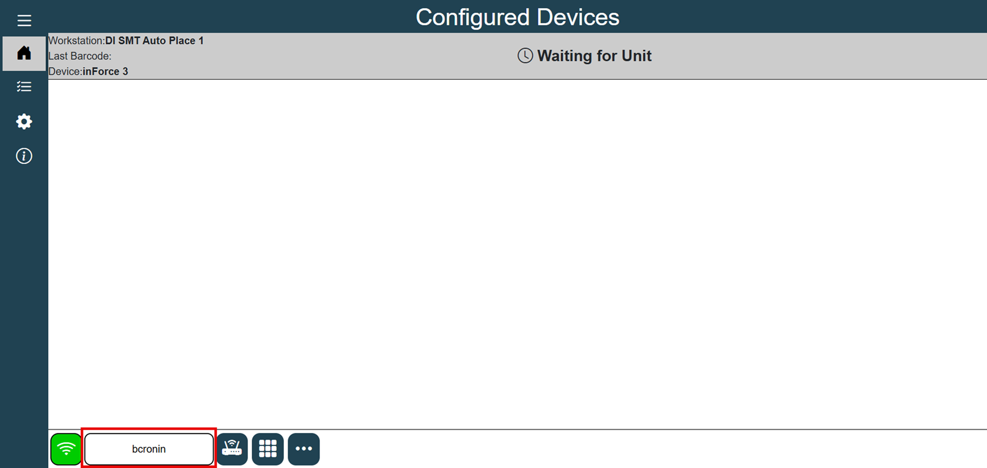
Once discovered, the display attached to the inForce device should reflect the following:
Manual xLink Server Configuration
Under certain circumstances, the Discovery mechanism may not be possible due to network topology or other factors. In this case, it is possible to manually specify the xLink Server name or IP address:
Attach a USB mouse and keyboard to the inForce device.
Enter the name or IP address of the xLink Server in the box in the lower-left area of the inForce user interface display, select Enter—then select the icon immediately to the right to connect to the xLink Server.
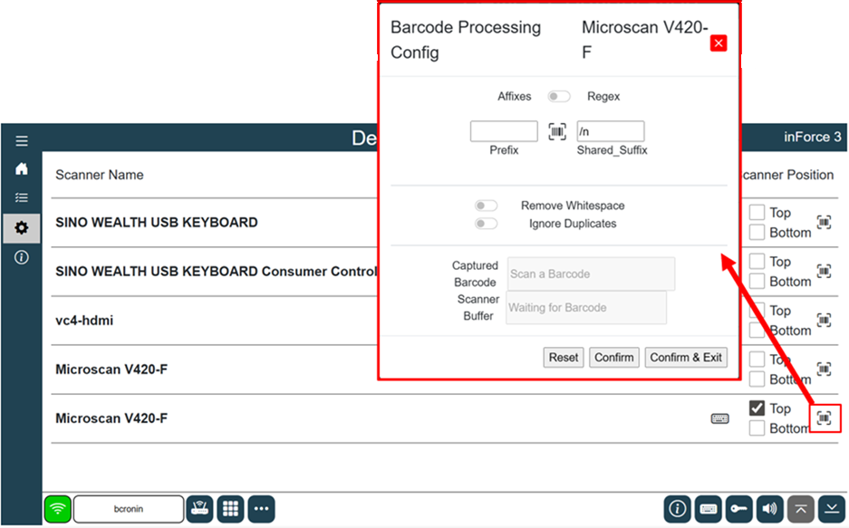
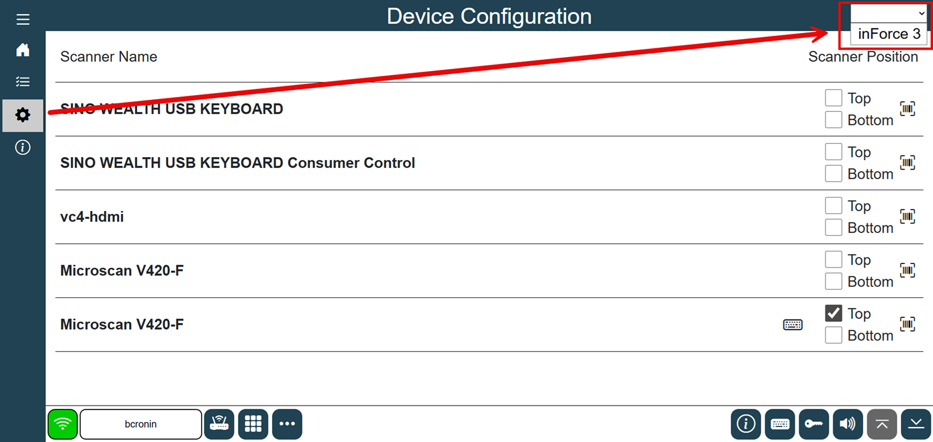
You will then need to specify which xLink adapter you want this device associated with:Select the cog wheel icon on the inForce device display in the left navigation bar (Device Configuration dialog), then select the xLink adapter instance from the selection in the upper-right area of the screen—we selected inForce 3 in the following example.
Note
These tasks must be done on the device itself, as the settings are not present in headless mode (where users are monitoring a unit remotely).
Once this task is accomplished, you may then configure any attached barcode scanners.
Barcode scanner setup
Select the cog wheel icon in the left navigation bar (Device Configuration dialog).
The setup screen allows users to define Top and Bottom barcode scanners, if applicable.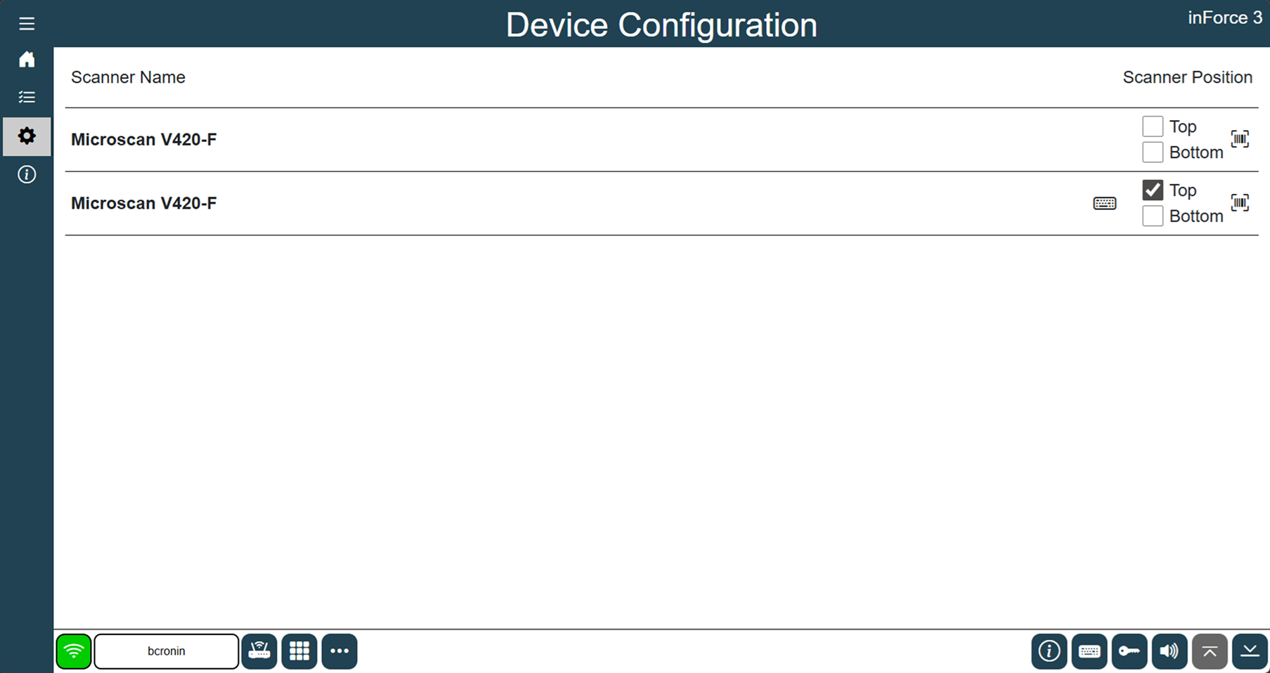
To associate a scanner with a specific board side, select the Detect Top Scanner or Detect Bottom Scanner button in the bottom toolbar (lower-right corner), then scan any barcode with the desired scanner.
Note
You may also manually select the appropriate check box (Top or Bottom) next to each scanner if you’re able to determine which one is Top and which one is Bottom. (In the previous illustration, we have two identical scanners attached, so the “detection” method would be necessary.)
Once the association is made, the inForce device will recognize which side of the board the scan is intended to represent—if these board sides are not configured, inForce will operate exactly like the first generation of inForce where the scan is simply associated to the next logical operation in the process flow that still needs a WIP record.
Each barcode scanner may be configured with a prefix and/or suffix. The default setting is a carriage return as the suffix. inForce will consider the scan complete once that character is received from the barcode scanner. The small barcode icon will open the settings and allow you to configure your scanner’s prefix and suffix.